
FEATURE| A Buyer’s Guide to Steel Welding Joints: Types, Grooves, Penetration & Standards
Welding is ubiquitous in international steel trade. From beam-column joints in steel structures, circumferential welds in oil and gas pipelines, and cross welds in steel mesh to end connections in mining anchors, welding quality directly determines the safety and durability of these products under service conditions. However, many international buyers focus on the chemical composition, mechanical properties and dimensional tolerances of the base material when purchasing, but do not pay enough attention to the quality control of the welded joint itself.
The core challenge in welding quality lies in the fact that, unlike the base material, it cannot be proven by a material certificate. For this reason, ISO 9001:2015 considers welding as a “special process”—its quality cannot be easily verified in subsequent inspections and must be controlled during the process. An incomplete root weld may become a crack initiation under fatigue load; a steel mesh with insufficient weld strength may fall apart during construction; a batch of steel structural components using the wrong welding materials may fracture brittlely at low temperatures. These problems are often not visible to the naked eye during the acceptance inspection upon arrival, but they are exposed during installation or when the load is borne, bringing not only safety risks, but also a chain reaction of costs such as rework, claims and project delays.
This article, from the perspective of international buyers, systematically reviews the selection logic of welding joint types and weld forms, bevel and edge preparation, full penetration and partial penetration, common welding misconceptions, selection factors for joint types, as well as the international welding standard system and key points for procurement verification. The aim is to help buyers accurately identify key technical aspects, reasonably agree on contract terms, and verify the supplier's welding capabilities through documentation and inspection when dealing with welded steel products.
1.Types of welded joints and weld forms
1.1 Five Types of Welded Joints
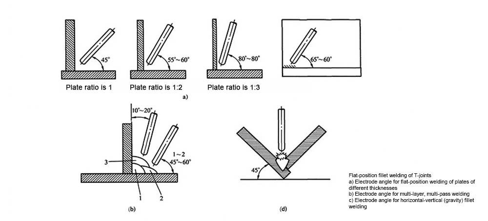
There are five primary types of welded joints: butt joints, T-joints, corner joints, lap joints, and edge joints. Among these, butt joints and T-joints are the most frequently used in steel structures. In a butt joint, the two components lie in the same plane with their edges facing each other; this configuration ensures uniform load transfer and avoids significant stress concentrations, making it the preferred choice for critical load-bearing welds. A T-joint is formed when the end face of one component intersects the surface of another at a right angle or an angle approximating a right angle; typically utilizing double-sided fillet welds or groove welds, it is the most common joint configuration found in steel structural frames, crane girder webs, and machine bases.
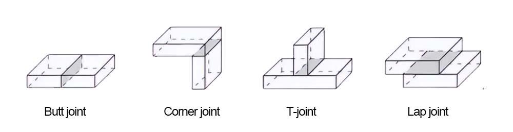
1.1.1 Butt joint: Place two flat metal pieces side by side so that their edges touch. It has uniform stress distribution and high strength under both static and dynamic loads. It also has a flat and aesthetically pleasing appearance, making it the most widely used joint type. However, it requires high standards for pre-welding preparation and assembly.
1.1.2 T-joint: Connect two pieces of material at a right angle to form a T-shape. Widely used for spatial weldments and characterized by high strength, T-joints account for approximately 70% of the welds in ship hull structures.
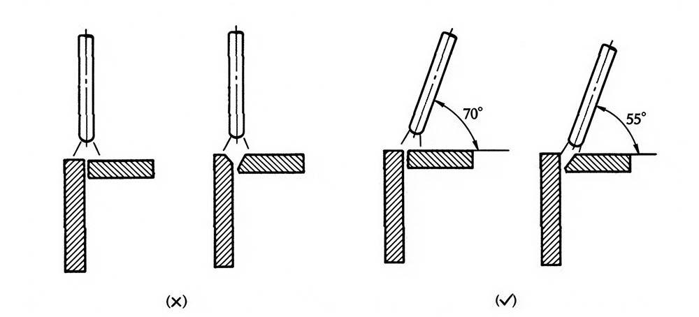
1.1.3 Corner joint: Connects two pieces of wood at a 90-degree angle, typically at the edge of a frame. It typically only serves as a connection and can only be used to transmit working loads.
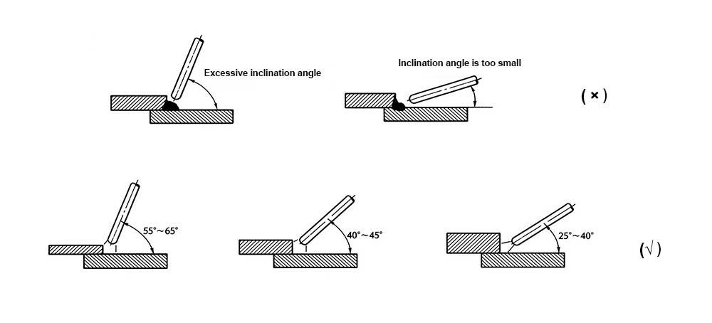
1.1.4 Lap joint: Two pieces of metal are overlapped together, usually used when they are of different thicknesses. The preparation before welding is simple, but it generates additional bending stress when subjected to force, which reduces the joint strength.
1.1.5 Edge joint: The edges of two welded parts intersect at a certain angle, usually used for thin plate structures or sealing connections. With low load-bearing capacity, it is generally only used for connection or sealing and is not used to transmit the main working load. Commonly found at the ends of thin-walled containers, pipe seals, and edge connections of sheet metal parts.
1.2 Six Types of Weld joint types
Weld joint types can be divided into six types: T-joint weld, butt weld, fillet weld, plug weld, groove weld, and end weld. The most commonly used types are butt weld, fillet weld, and plug weld.
1.2.1 T-weld: A T-weld is formed when two workpieces are joined at a 90° angle. In this type of weld, the edge of one workpiece is welded to the center of the plane of another workpiece to form a T-shape. T-welds can also be formed when pipes or tubes are welded to the base plate. These types of welds have high mechanical strength, especially when welded from both sides. T-welds are used in many manufacturing applications, including pipes, structural steel, and equipment.

1.2.2 Butt weld: A weld formed between the bevel surfaces of two workpieces or between the bevel surface of one part and the surface of another part. Butt welds typically require full penetration, uniform stress distribution, and high load-bearing capacity, making them the preferred weld type for important load-bearing structures. It is commonly found in critical parts such as longitudinal and circumferential seams of steel pipes, steel plate splicing, and flange butt joints of beams and columns.

1.2.3 Fillet weld: When two workpieces are welded from 90° to an L-shape, a fillet weld is formed. A weld formed along the intersection line of two orthogonal or nearly orthogonal parts. Its cross-section is triangular, and shear force is transmitted through the effective throat of the weld. Fillet welds are simple to process and do not require beveling, making them the most common type of weld among T-joints, lap joints, and corner joints. However, fillet welds do not perform as well as full penetration butt welds in terms of fatigue performance, and should be used with caution in critical nodes subjected to dynamic or fatigue loads.

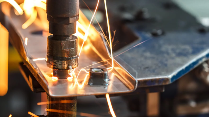
1.2.4 Plug weld: When two parts are stacked, one of them has a round hole, and the two plates are welded into the round hole to form a weld. If only a fillet weld is welded in the hole, it is not called a plug weld. Plug welds are mainly used in lap joints, where two plates are joined together by filling the hole with weld metal. They are commonly used for the connection and reinforcement of thin plate structures.
1.2.5 Slot weld: Two plates are stacked together, one of which has an elongated hole. The weld between the two plates is then made in the elongated hole. Similarly, if only a fillet weld is made, it is not called a slot weld. The function of a slot weld is similar to that of a plug weld, but the shape of the elongated hole makes it suitable for lap joints that require a larger connection area or a longer weld length.
1.2.6 Edge weld: The weld formed to constitute a termination joint. The edges of the two welded parts of the termination joint intersect at a certain angle. It is usually used for thin plate structures or sealing connections. It has a low load-bearing capacity and generally only serves as a connection or sealing function, and is not used to transmit the main working load. Commonly found at the ends of thin-walled containers, pipe seals, and edge connections of sheet metal parts.

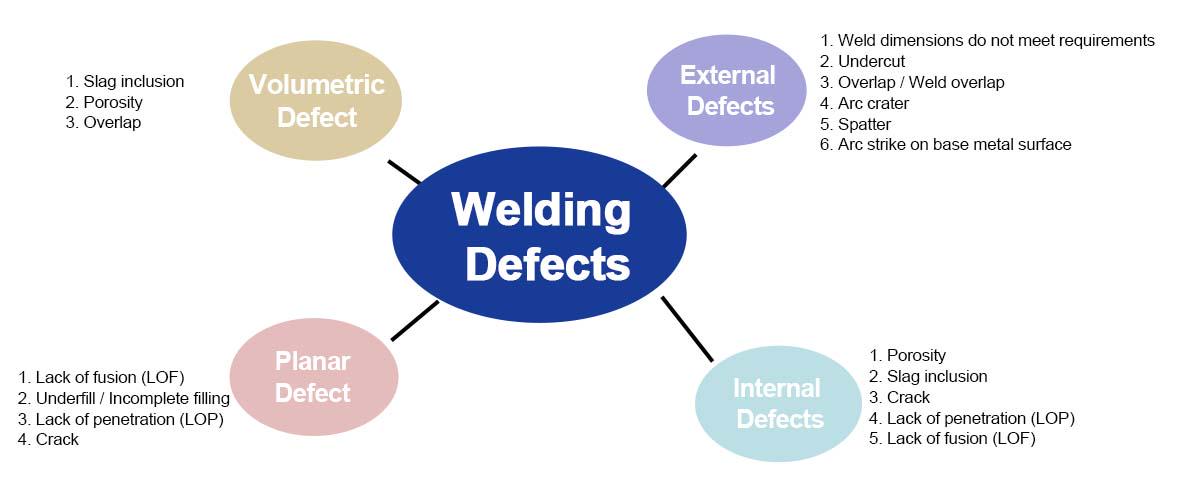
It is important to note that the names of joint types and weld forms differ under different standard systems. AWS A2.4 and ISO 2553 specify the methods for marking welding symbols in the United States and ISO systems, respectively. ISO 2553 is the welding symbol standard widely used in international practice. When procuring welding products, it is essential to confirm whether the welding symbol system used by the supplier is consistent with the standards specified for the project, in order to avoid incorrect joint configurations due to misunderstandings of the drawings.
2. Common Welding Groove and Edge Preparation
The bevel is the geometric basis of the bevel weld, while edge preparation is a process that must be completed before welding. For buyers, understanding the basic logic of beveling and edge preparation helps them determine whether a supplier's quote is reasonable and whether the process is up to standard, and also helps them identify welding defects caused by improper beveling during the inspection upon arrival.
2.1 Classification and Selection Logic of Bevel Forms
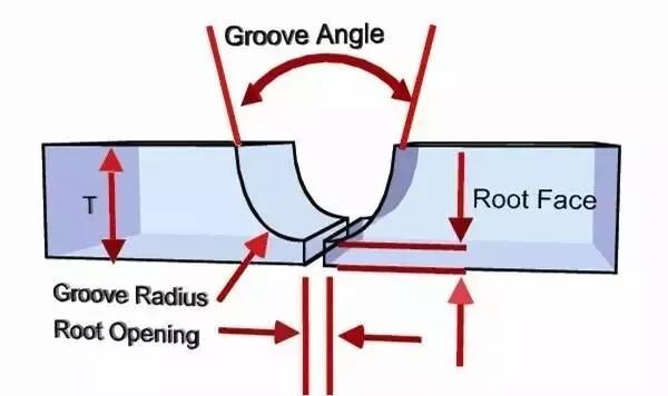
To ensure welding quality, the workpiece needs to be processed before welding. This can be done by gas cutting or cutting, and is generally a bevel, but sometimes a curved surface. For example, if two 10mm thick steel plates are to be welded together, a chamfer will be milled on the edge of the plate to ensure a strong weld. This is called beveling. Due to differences in material thickness and welding quality requirements, the welding joint type and bevel shape are also different. Generally, bevel types are divided into K type, V type, I type, U type and X type, etc.
Beveling: K-type, V-type, I-type, U-type, and X-type, etc.
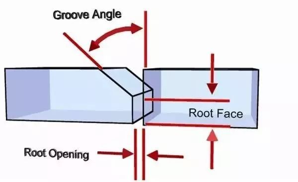
2.1.1 Single-bevel groove with root face
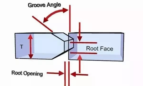
2.1.2 Double-bevel groove
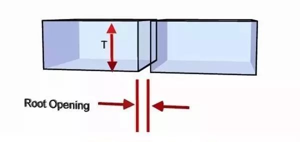
2.1.3 Square groove
2.1.4 Single V groove
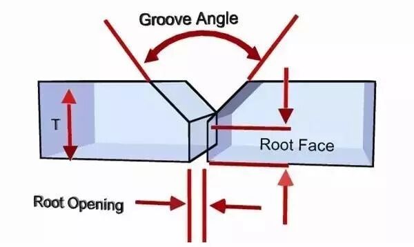
2.1.5 Double-V groove
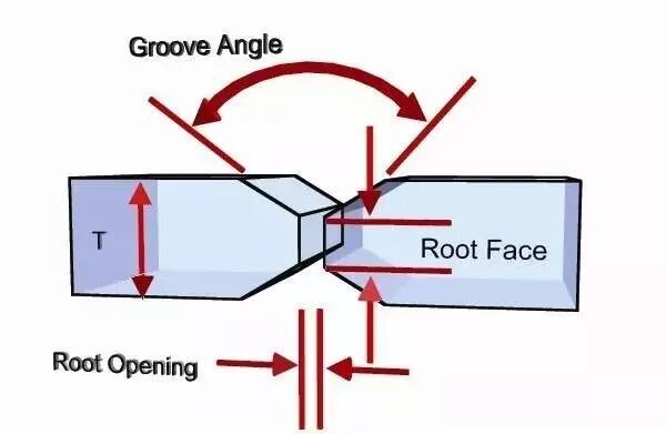
2.1.6 J-groove
Single-J groove
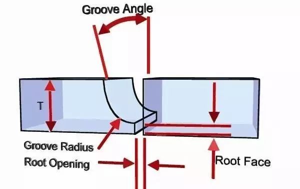
Double-J groove
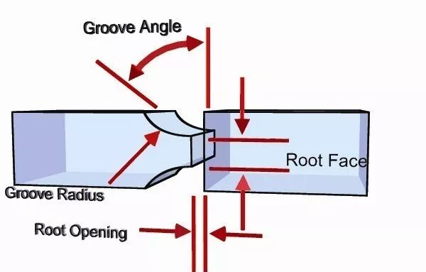
2.1.7 U-groove
2.2 Quality requirements and cleaning scope for edge preparation
After the beveling is completed, the quality of edge preparation also affects the welding result. Thermal cutting (such as flame cutting or plasma cutting) leaves oxide scale and a hardened layer of a certain thickness on the bevel surface. If these are not removed before welding, the first weld may not be able to fully fuse with the base material, resulting in incomplete fusion defects. Therefore, for critical joints requiring full penetration, the bevel surface usually needs to be machined (such as planing or milling) to remove the thermal cutting influence layer, or the thermally cut surface needs to be polished until the metal luster is exposed.
Before welding, the surface of the base material within a certain range on both sides of the bevel must be cleaned to remove water, rust, oil, scale and other impurities. Different standards do not have entirely consistent requirements for the scope of this cleanup. Steel structure standards (such as GB 50661-2011) typically specify a 30 mm range on each side of the bevel edge; pressure vessel standards (such as NB/T 47015-2023) uniformly specify 20 mm. Aluminum pressure vessels require a larger cleaning range, up to 50 mm. For galvanized steel, the galvanized layer needs to be removed within a range of at least 25 mm on both sides of the weld before welding; otherwise, the evaporation of zinc will lead to porosity and incomplete fusion.
The Influence of Base Metal Impurities on Weld Quality
a.Moisture
(1) The presence of water can cause hydrogen-induced cracking. When moisture is present during the welding process, it decomposes, releasing hydrogen into the molten pool. Hydrogen may become trapped in the weld during cooling and solidification, leading to internal cracks, affecting mechanical properties, and reducing weld strength (due to increased diffusible hydrogen content).
(2) Hydrogen formed during the decomposition of moisture may lead to the formation of hydrogen pores if it does not escape in time.
(3) Electrodes can cause arc instability. The evaporation of moisture produces gas, which disrupts the stability of the electric arc and thus reduces the welding quality.
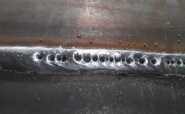 pores
pores
b.Oils and greases
These substances can form a barrier between the welding material and the base material, resulting in poor adhesion and potential welding defects. When subjected to high-temperature welding, they also produce harmful gases, which can damage the welder's health.
c. Oxide Scale
(1) Formation of Pores: Oxide scale decomposes at high temperatures, forming oxygen pores.
4FeO --(>1370°C)--> Fe₃O₄ + Fe + O₂↑
(2) Formation of Unfused Metals: The melting point of iron oxide is higher than that of steel.
(3) The porous surface of Fe0 easily absorbs moisture, and moisture decomposition causes hydrogen-induced cracking and hydrogen porosity.
(4) Slag inclusions in welds: In addition to iron oxide, the surface of the oxide scale contains other impurities such as sulfides and manganese.
(5) Reduced weld strength: Foreign literature shows that not removing the oxide layer results in a 10% decrease in yield strength, an 8.5% decrease in tensile strength, and a 60% decrease in impact toughness compared to removing the oxide scale.
(6) Differences in surface quality:
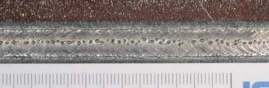
With oxide scale: After welding, the surface will have a "scale-like" appearance.
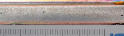
No oxide scale: The surface is clean after welding.
d.Rust.
It is thinner than oxide scale. Rust on the welded surface can cause pores in the weld, forming small holes in the weld bead, thereby weakening its overall strength. Rust can also hinder the flow of the molten pool, leading to uneven welds.
2.3 The appearance quality of welds shall meet the following requirements:
2.3.1 Grade I welds shall be free from defects such as incomplete fusion, root shrinkage, undercut, and poor joints. Grade I and Grade II welds shall be free from defects such as surface porosity, slag inclusions, cracks, and arc strikes.
2.3.2 In addition to meeting the requirements of paragraph 1 of this article, the appearance quality of Grade II welds shall also meet the relevant requirements in the table below.
2.3.3 The appearance quality of Grade III welds shall meet the relevant requirements in the table below.
| Inspection Item | Grade II | Grade III |
| Incomplete filling / Underfill | ≤0.2+0.02t and ≤1mm; cumulative length ≤25mm per 100mm of weld length | ≤0.2+0.04t and ≤2mm; cumulative length ≤25mm per 100mm of weld length |
| Root concavity / Root shrinkage | ≤0.2+0.02t and ≤1mm; length unlimited | ≤0.2+0.04t and ≤2mm; length unlimited |
| Undercut | ≤0.05t and ≤0.5mm; continuous length ≤100mm; total undercut on both sides ≤10% of total weld length | ≤0.1t and ≤1mm; length unlimited |
| Crack | Not permitted | Crater cracks with length ≤5mm permitted |
| Arc strike | Not permitted | Individual arc strikes permitted |
| Poor joint / Joint defect | Notch depth ≤0.05t and ≤0.5mm; max. 1 location per 1000mm of weld length | Notch depth ≤0.1t and ≤1mm; max. 1 location per 1000mm of weld length |
| Surface porosity | Not permitted | 2 pores permitted per 50mm of weld length, diameter ≤0.4t and ≤3mm; spacing ≥6 times pore diameter |
| Surface slag inclusion | Not permitted | Depth ≤0.2t; length ≤0.5t and ≤20mm |
Quality issues to be aware of:
(1) Dimensions exceeding allowable deviations: For deviations such as insufficient length, width, or thickness of the weld, centerline offset, or bending, the relative positional dimensions of the welded parts should be strictly controlled. Welding is only permitted after the dimensions are qualified, and careful operation is required during welding.
(2) Weld cracks: To prevent cracks from forming, appropriate welding process parameters and welding procedures should be selected. Avoid using high current and do not suddenly extinguish the flame. The weld joint should overlap by 10- 15 mm. During welding, it is not allowed to move or knock the weldment.
(3) Surface porosity: The welding rod is baked at the specified temperature and time; the welding area must be cleaned, and an appropriate welding current is selected during the welding process. The welding speed is reduced to allow the gas in the molten pool to escape completely.
The procurement contract should specify the method of beveling (thermal cutting or mechanical processing), the quality requirements for the bevel surface, and the scope and standards of pre-welding cleaning. If the supplier cannot provide inspection records for the beveling process, the buyer can request a spot check of the actual dimensions of the beveling angle, root clearance, and blunt edge during the pre-shipment inspection to confirm whether they are within the standard allowable tolerances.
3. Full penetration and partial penetration
Full penetration: The entire thickness of the base material is melted through in one go from the welding side, forming a weld bead on the back side (single-sided welding with double-sided forming)
The phenomenon of complete melting through the root of the joint during welding is called full penetration.
Here, welding refers to melting through the root of the joint using welding methods. However, this root is not necessarily on the other side of the base material; it may also be in the middle of the double-sided weld.
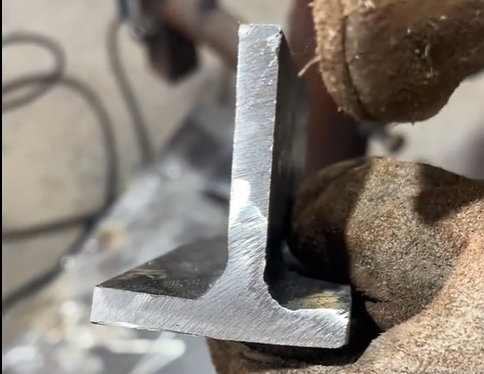
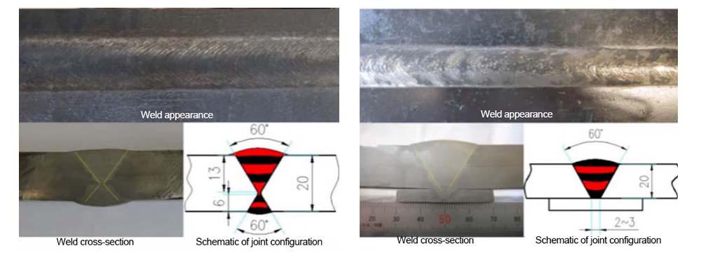
3.1 Full Penetration Welding
Full penetration welding refers to welding a joint in which the weld extends through the entire thickness of the workpiece, thus completely connecting the two workpieces together. During welding, the welding rod or electrode will use appropriate technical means to make the weld reach or exceed the full thickness of the workpiece, and the entire weld will be in a completely molten state, with the weld connection completely penetrating the workpiece.
3.2 Partial Penetration Welding
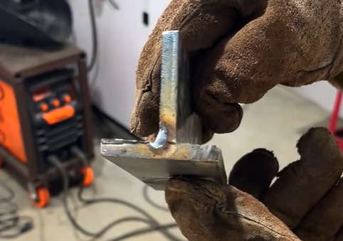
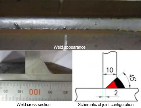
Partial penetration refers to the welding process where the weld only partially penetrates the thickness of the workpiece and does not completely penetrate the entire workpiece. During welding, the welding rod or electrode is used only on one side of the joint, resulting in a shallow weld depth that does not fully reach the other side of the workpiece.
Difference:
Welding depth: The depth of a semi-penetrating weld is insufficient for the thickness of the workpiece, while the depth of a full-penetrating weld can reach or exceed the thickness of the workpiece.
Strength: Because full penetration welds can completely penetrate the weldment, they have relatively higher structural strength. A semi-penetrating weld only partially penetrates the workpiece, resulting in lower welding strength compared to a fully penetrated weld.
Application scenarios: Semi-penetration welding is often used in applications where the strength requirements of the weldment are not high or the workpiece is relatively thin. It can reduce heat input and prevent excessive deformation. Full penetration welding is often used in applications requiring higher strength connections, such as structures subjected to large loads or pressures.
Welding process: Semi-penetration welding is relatively simple and easy to operate, but may require additional welding or other reinforcement measures. Full penetration welding is relatively complex and requires reasonable control of welding parameters and techniques to ensure that the weld completely penetrates the entire workpiece.
4.Common Welding Misconceptions
The root cause of welding quality problems is often not a lack of technical skill, but rather a misunderstanding of welding methods during the procurement and construction phases. The following is a summary of some of the most common welding mistakes.
Myth 1: Using a partially penetrated weld as a fully penetrated weld.
As mentioned above, a partially penetrated weld has an unfused surface at the root. Its load-bearing capacity is directly proportional to the penetration depth, and its fatigue performance is significantly lower than that of a fully penetrated weld. If the drawings indicate partial penetration, but the joint is subjected to tensile or fatigue loads not anticipated in the design during actual use, it may fail under conditions far below the design load.
Buyers need to confirm whether the bevel weld markings on the drawings are CJP or PJP and specify this in the contract. For critical nodes subjected to dynamic loads or seismic requirements, full penetration welds should be insisted upon.
· CJP—Complete Joint Penetration.
· PJP—Partial Joint Penetration.
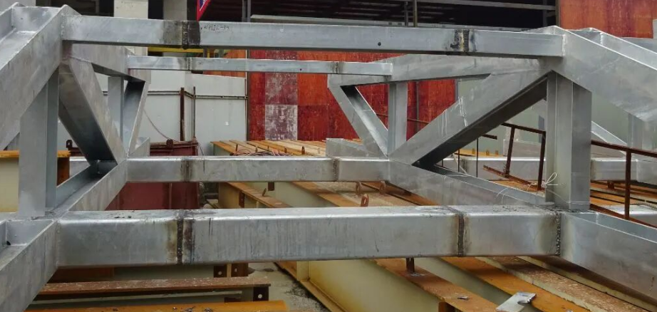
Myth 2: The zinc layer is not removed before welding galvanized steel.
The zinc layer evaporates under the high temperature of the welding arc, producing zinc vapor, which leads to porosity and incomplete fusion in the weld.
For galvanized sheets or pipes with medium wall thickness (3mm or more), in order to reduce the negative impact of the galvanized layer on the weld, the galvanized layer inside the bevel should be removed before welding. Even for hot-dip galvanized steel, the galvanized layer must be removed from at least 25 mm on both sides of the weld before welding. If construction conditions do not allow for the removal of the galvanized layer inside the bevel, then the maximum possible heat input should be used to melt, vaporize, and evaporate the zinc layer to escape from the weld surface, thereby reducing the residue of zinc (Zn) in the weld. In particular, by employing welding techniques such as multi-layer multi-pass welding, repeated welding in the same position, and back-and-forth electrode manipulation, relatively ideal weld mechanical properties can be obtained. After welding is completed, the anti-corrosion layer in the weld area also needs to be repaired. When purchasing galvanized welded products, it should be confirmed whether the supplier has performed this process.
Myth 3: Only looking at the welder's qualification certificate, not the welding procedure qualification certificate.
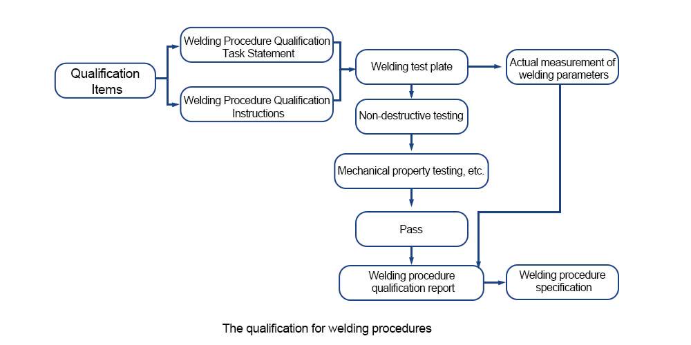
A welder's qualification certificate proves that the welder has the operating skills, but the welding procedure qualification certificate (PQR) proves that the welding procedure itself has been tested and meets the standard requirements. Even if a supplier has a qualified team of welders, but lacks PQR (Preliminary Quality Rating) for specific joint types and base material combinations, the weld quality still lacks systematic assurance.
When procuring welded structural components, three documents should be required simultaneously: WPS, PQR, and welder qualification record. All three are indispensable.
Myth 4: Using the wrong strength grade of welding materials.
When welding low-alloy high-strength steel, if welding materials that do not match the strength of the base material are used, it may result in insufficient weld strength or excessive hardness. E7018 low-hydrogen welding electrodes are commonly used for structural carbon steel, but when welding high-strength steel or joints requiring low-temperature toughness, matching welding materials must be selected. The selection of welding materials should be clearly specified in the WPS, and the supplier should be required to provide a quality certificate for the welding materials in the purchase contract.
Myth 5: The larger the bevel angle, the better the welding.
An excessively large bevel angle will increase the amount of filler metal used and welding deformation, while an excessively small bevel angle will cause the welding torch to fail to reach the root and result in incomplete fusion. The bevel angle, root clearance, and blunt edge must be matched. If any one of them exceeds the allowable tolerance range of the standard, it may lead to unqualified welding quality.
The tolerance requirements for the bevel type should be clearly specified in the procurement contract, and the actual dimensions should be checked during the pre-shipment inspection.
Myth 6: Neglecting pre-weld cleaning and interlayer cleaning.
Misconception: Failing to clean oil and rust from the base material surface before welding, or failing to clean weld slag before directly covering the surface, can lead to porosity and slag inclusions inside the weld.
Correct understanding: Thorough grinding and cleaning are essential before welding, and slag removal and grinding are necessary between layers. This is the foundation for ensuring the internal quality of the weld.
5. Factors in selecting the type of welded joint
The previous article introduced five basic types of joints: butt joints, T-joints, corner joints, lap joints, and end joints, as well as the stress characteristics and typical applications of each type. In actual procurement, the problem faced by buyers is not "what types of connectors are available", but rather "which connector should be used for this product". The choice of joint type is not a matter of personal preference for designers, but rather a result of a comprehensive balance of load conditions, plate thickness, welding methods, and manufacturing costs. For international buyers, understanding these factors helps them determine whether the welding solutions proposed by suppliers are reasonable and also allows them to ask targeted questions during the technical clarification phase.
Load type is the primary factor. For critical joints subjected to tensile, bending, and fatigue loads, fully penetrated butt joints or T-groove joints must be used. For connections under static or compressive load conditions, fillet welds or partially penetrated groove welds can be used. For seismically designed structures, the bevel welds at beam-column joints must also meet additional toughness requirements. If the supplier uses fillet welds instead of full penetration groove welds at critical load-bearing nodes, the buyer needs to request that the supplier provide design justification and confirm whether it has been reviewed by a structural engineer.
Plate thickness determines the bevel type and welding method. Thin plates can be welded directly without beveling, medium and thick plates require V-shaped or X-shaped beveling, and thick plates tend to have U-shaped beveling to reduce filler and deformation. When the thicknesses of the two plates differ significantly, the thicker plate needs to be thinned to avoid stress concentration at the joint. This factor directly affects welding costs and time, and is also a significant source of differences in supplier quotes.
The accessibility of welding methods affects joint design. If the joint can only be welded from one side, a single-sided bevel design with a liner is required. If welding space is limited, a narrow-gap bevel should be used to reduce the amount of filler. For automated welding joints, the consistency requirements for bevels are even higher. In procurement, if a supplier proposes a certain joint type because "this is the only way to weld on site," the buyer needs to confirm whether this adjustment has been approved by the designer.
Accessibility should also be considered. Some joint types cannot be subjected to ultrasonic or radiographic testing after welding and can only rely on visual inspection and surface testing. For critical joints requiring full penetration, quality verification cannot be implemented if inspection accessibility is insufficient. The procurement contract should specify the inspection method and confirm whether the selected connector type supports the inspection method.
Cost is a practical constraint. Butt joints use less material and transmit force evenly, but they have strict requirements for material dimensions, and the beveling process increases costs. Fillet welds do not require beveling, but their performance under fatigue loads is not as good as full penetration bevel welds. In practical design, a balance needs to be found between safety and economy. Buyers should avoid two tendencies: first, accepting a lower welding grade in order to lower the price; and second, demanding full penetration of all joints without considering the actual load conditions.
6. Welding standards and selection
Welding standards are not isolated documents, but a multi-level system. Welding standards can ensure that the welding process conforms to unified industrial standards; improve the controllability and consistency of welding quality; strengthen inter-industry communication and cooperation; and facilitate international trade of products. For international buyers, understanding the hierarchical structure of this system helps to accurately specify technical requirements in contracts and effectively verify the welding capabilities of suppliers during the procurement process.
Welding standards cover five dimensions: Construction and Product, Process Qualification (WPS/PQR), Welder Qualification (WPQ), Non-destructive Testing (NDT), and Quality Management (ISO 3834).
Welding standards hold an important position globally, with relevant regulations both domestically and internationally.
6.1 Chinese National and Industry Standards for Welding and Related Applications
| Standard No. | Standard Title | Administering Body | Applicable Field |
| GB/T 19869.1 | Welding procedure qualification test for steels, nickel and nickel alloys | SAC/TC55 | Welding procedure qualification |
| GB/T 3323.1 / 3323.2 | Non-destructive testing of welds — Radiographic testing — Part 1: Film techniques; Part 2: Digital detector technologies | SAC/TC55 | Radiographic testing of welds |
| GB/T 150 (series) | Pressure vessels (Part 1: General requirements, etc.) | SAC/TC262 | Design, fabrication and inspection of pressure vessels |
| GB 50661 | Code for welding of steel structures | MOHURD | Welding of steel structures |
| NB/T 47014 | Welding procedure qualification for pressure equipment | SAC/TC262 | Welding procedure qualification for pressure equipment |
6.2 International and Regional Welding-Related Standards
Internationally, ISO is the main body responsible for developing welding-related standards, specifically ISO/TC 44 (Welding and Related Processes). The International Institute of Welding (IIW), as a global welding organization, collaborates with ISO/TC 44 and provides technical support, but is not a direct issuing body for ISO standards.
European regional standards are developed by CEN (European Committee for Standardization), with CEN/TC 135 responsible for the implementation standards for steel and aluminum structures. Common standards include:
| Standard No. | Standard Title | Administering Body | Applicable Field |
| ISO 3834 (series) | Quality requirements for fusion welding of metallic materials | ISO/TC 44/SC 10 (in collaboration with IIW) | Welding quality control |
| ISO 14731 | Welding coordination — Tasks and responsibilities | ISO/TC 44/SC 11 (IIW certification scheme) | Welding personnel qualification |
| ISO 8501 (series) | Preparation of steel substrates before application of paints and related products — Visual assessment of surface cleanliness | ISO/TC 35/SC 12 | Steel surface preparation |
| EN 1090 (series) | Execution of steel structures and aluminium structures | CEN/TC 135 | Welding of steel and aluminium structures |
6.3 Comparison of Major Global Welding Standard Systems
| System | Representative Standards | Applicable Fields |
| China | GB 50661 / NB/T 47014 / GB/T 19869 | Steel structures / Pressure vessels / Piping |
| USA | AWS D1.1 / ASME Section IX | Steel structures / Pressure vessels / Bridges |
| EU | EN 1090 / EN ISO 15614 | Steel structures / Pressure equipment |
| International | ISO 3834 / ISO 15614 / ISO 9606 | Cross-border projects / Export manufacturing |
Construction and product standards are the level that buyers have the most direct contact with, as they stipulate "how to make the product and how to judge the acceptance."
AWS D1.1-2025: American Institute of Welding's steel structure welding standard, the most widely used standard in the world. It consists of 11 chapters, covering connection design, pre-certification WPS, qualification certification, manufacturing, inspection, stud welding, tubular structures and reinforcement repair; applicable to structural steel with a thickness ≥3mm and a yield strength ≤690MPa.
ASME Section IX-2025: The core standard for boiler and pressure vessel welding, which specifies the WPS, PQR, and WPQ evaluation rules and is referenced in all volumes of BPVC; however, it only involves process and personnel qualification evaluation and does not include production weld acceptance standards. Acceptance is specified by construction codes such as ASME Section VIII and B31.3.
EN 1090-2: The EU execution standard for steel structures; mandatory since 2012, it serves as a necessary basis for CE marking. The execution levels are EXC1–EXC4: EXC1 is for low-risk, simple structures; EXC2 is for steel structures and conventional bridges; EXC3 is for long-span bridges and high-rise buildings; and EXC4 is for special, complex structures and nuclear-grade equipment.
GB 50661-2024: Chinese Code for Welding of Steel Structures, applicable to steel structures with static/dynamic loads and a thickness ≥3mm, covering welding methods, bevel forms, process qualification, quality inspection and rework, etc.
Key differences: AWS, EN, and GB focus on product construction and acceptance; ASME IX only governs processes and personnel qualifications, with production acceptance handled separately according to construction specifications.
The process qualification standard specifies how welding processes are qualified, and usually covers welding methods (gas shielded arc welding (GMAW), argon arc welding (TIG welding), electric arc welding) and welding parameters (current, voltage, speed, etc.). These parameters must be strictly controlled during operation to ensure the quality of the welded joint.
SME Section IX categorizes variables into critical variables (those outside the assessment range require a new PQR), supplementary critical variables (applicable only when impact testing is required), and non-critical variables (which can be modified in WPS without reassessment). WPS uses QW-482, and PQR uses QW-483. One PQR can support multiple WPSs, as long as the critical variables are within the assessment range.
The ISO 15614 series corresponds to the ASME PQR requirements. ISO 15614-1 specifies the qualification methods for arc welding/gas welding of steel and arc welding of nickel alloys, which are divided into two levels. Level 2 tests are broader and more stringent, automatically covering Level 1.
China's GB/T 19869.1-2023 is equivalent to ISO 15614-1:2017, and its technical content and evaluation rules are consistent.
Quality management system standards specify the type of quality system that welding enterprises are required to establish.
Welding quality control is a crucial part of the entire process and primarily comprises: welding inspection—such as visual inspection, ultrasonic testing and radiographic testing—to ensure that welded joints meet the specified quality requirements; and welding records—detailed records of each welding operation, including the welder, welding parameters and inspection results—to facilitate traceability at a later date.
The ISO 3834 series is a set of standards developed by the International Organisation for Standardisation (ISO) to ensure welding quality. It specifies the quality requirements for fusion welding of metallic materials and provides a basis for assessing manufacturers’ welding capabilities. The series is divided into three quality levels: ISO 3834-2 (comprehensive quality requirements), ISO 3834-3 (general quality requirements) and ISO 3834-4 (basic quality requirements). For buyers procuring welded structural components, whether a supplier has established an ISO 3834 system is a key indicator for assessing its welding quality management capabilities.
EN 1090-2 establishes a direct correspondence between execution classes (EXC) and the quality requirement levels of ISO 3834: EXC1 corresponds to basic quality requirements (ISO 3834-4), EXC2 corresponds to standard quality requirements (ISO 3834-3), and EXC3 and EXC4 correspond to comprehensive quality requirements (ISO 3834-2).
Welding examination standards specify how welders are assessed and how qualifications are awarded. Welders are typically required to undergo specialist training and obtain certification.
The ISO 9606 series is widely adopted internationally as the standard for fusion welding examinations; examination parameters include welding process, base metal group, welding position (1G–6G for pipes, 1F–4F for plates) and weld type, amongst others.
AWS D1.1 also sets out requirements for welder qualification: welders must hold a current Welder Performance Qualification Record (WPQR) issued by the manufacturer and maintain their qualification by submitting welding records every six months. The traditional European standard EN 287 has now been harmonised with ISO 9606.
When procuring welded products, it is essential to verify that the welder’s qualification is valid and that the examination conditions (base metal, position, method) cover the actual production operations.
Non-destructive testing and acceptance standards specify how weld defects are classified and inspected.
ISO 5817 is the core standard for the quality classification of weld defects; it applies to fusion-welded joints in steel, nickel, titanium and their alloys, and specifies three quality grades: B (strict), C (moderate) and D (general), with Grade B corresponding to the highest weld quality requirements. The applicable standard specifies which grade is to be adopted. ISO 17635 specifies general guidelines for non-destructive testing, whilst ISO 17636 and ISO 17637 specify the specific methods for radiographic testing and visual inspection, respectively.
With regard to inspection methods, visual inspection is mandatory for 100 per cent of welds; radiographic testing is carried out in accordance with AWS D1.1 Annex M or EN ISO 17636-1; ultrasonic testing is carried out in accordance with AWS D1.1 Annex E or EN ISO 15624; and magnetic particle testing and penetrant testing are carried out in accordance with EN ISO 17638 and EN ISO 3452-1 respectively. For full-penetration joints, radiographic or ultrasonic testing is usually required; for fillet welds, visual and magnetic particle testing are generally sufficient.
When procuring, the WPS, PQR and welder qualification records should be verified: the WPS provides guidance on welding procedures, the PQR certifies that the process has been validated, and the qualification records attest to the personnel’s skills; together, these three elements constitute the assurance of welding compliance. If only a welder’s qualification certificate is provided without a WPS or PQR, this indicates a lack of systematic process validation.
Procurement contracts should clearly specify: the standards framework and version year, the acceptance grade (e.g. ISO 5817 Level B or the relevant requirements of AWS D1.1), non-destructive testing methods (VT/UT/RT/MT) and the procedure for handling non-conforming welds. It is essential to specify the version year of the standards to avoid situations where certificates or acceptance criteria based on outdated versions are not recognised by the project in the destination country or by customs authorities.
7. Development Trends of Welding Specifications and Standards
Welding specifications and standards will continue to evolve in the process of globalization. Future welding specifications and standards may move towards automation and intelligence, environmental protection and sustainability, multi-material welding, and international standardization. AI and robotics will drive intelligent welding control and quality monitoring; environmental regulations will promote low-emission, low-waste processes; the need for multi-material joining will drive continuous updates to standards; globalization will promote standard convergence; and ISO and IIW will play key roles.
Welding standards and technical specifications are updated frequently. International buyers should pay close attention to the updates of the welding standard versions and acceptance requirements applicable to the project in the target country, especially the version changes of core standards such as AWS D1.1, ASME Section IX, and ISO 15614. If you have any questions about the selection and procurement of welding methods, or are unsure about certain parameters (such as bevel type, penetration level, and acceptance criteria), please feel free to contact us and provide your project's technical specifications. CSMC will continue to monitor welding standards and technical information and actively provide more support to its customers.
We sincerely hope that the information we provide can make more beneficial value. In addition, we sincerely invite you to leave valuable comments and advice on our website. We will follow up on your comments and advice at any time on our website.
CSMC - Empowering small and medium-scale steel purchasing.
Editor: Hana Kyra
Mail: cs@chinasteelmarket.com



.png)
Copyright Notice © 2022 - 2023 ChinaSteelMarket.com All rights reserved.